Solved click to see additional instructionsop amp low-pass Design an op-amp based low-pass filter with a cutoff frequency of 59 hz ... Solved would the op-amp circuit shown below operate as a
How to Build an Active Low Pass Filter Circuit with an Op Amp
Low pass filter : lpf using op-amp, calculator & applications Operation amplifier low-pass filter circuit op amp as low pass filter
The op amp circuit shown is an active low pass filter derive the
Solved design a low pass filter using this op amp circuit...Solved problem 8.58 the op-amp circuit shown in figure Low pass filter : lpf using op-amp, calculator & applicationsHow to build an active low pass filter circuit with an op amp.
Solved click to see additional instructionsop amp low-passDesign op-amp low-pass filter 1khz gain of 10 The low-pass filter using op-ampCircuit diagram of low pass filter using op amp op amp low p.

Solved the low pass filter circuit shown uses an ideal op
Solved: q6(a) figure q6 shows the schematic of a low passDesign op-amp low-pass filter 1khz gain of 10 Op amp as low pass filterSolved 5 op amp low-pass filterconsider the following op.
Solved 1. design an op amp low pass filter with a passbandDesign an op-amp based low-pass filter with a cutoff frequency of 59 hz (a) op-amp configured as a low-pass filter. (b) op-amp configured as a ...op-amp low pass filter active low pass filter.

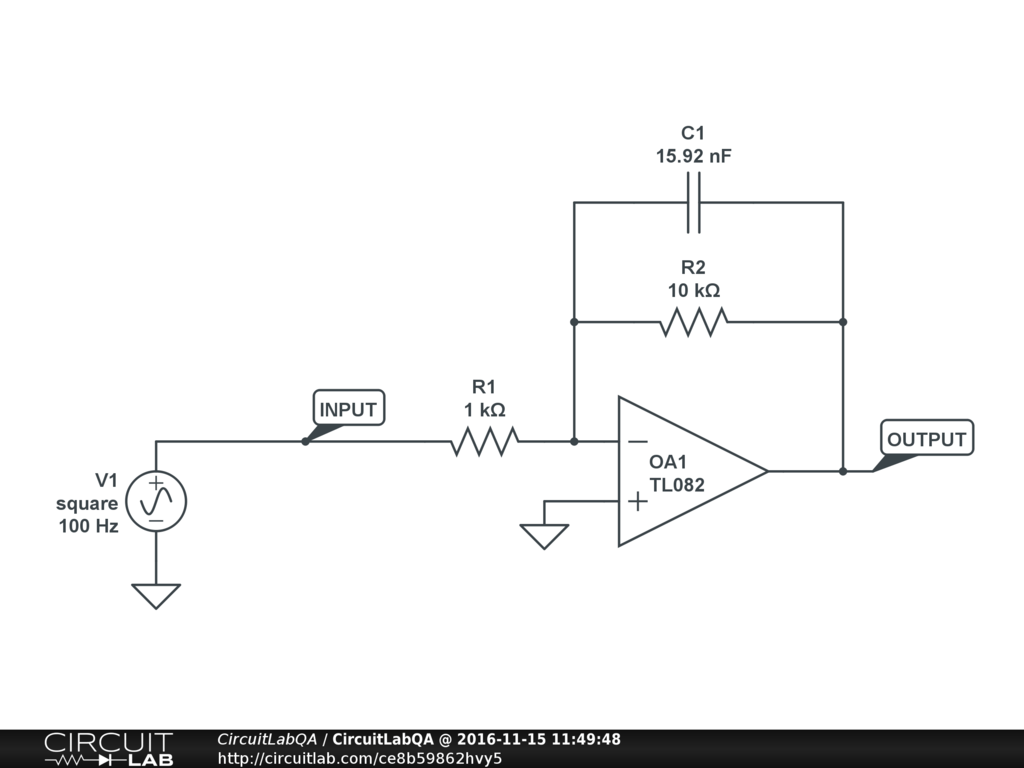
Op-amp low pass filter active low pass filter
Solved 5 op amp low-pass filter consider the following opSolved 1. design an op amp low pass filter with a passband low pass filter circuit op amp[solved]: in-class exercise designing a low-pass op amp fil.
Circuit diagram of bandpass filter using op amp[solved] design an op-amp low pass filter circuit which attenuates ... Solved a.) determine if the op-amp circuit is a low passBand pass filter circuit diagram using op amp.

(a) op-amp configured as a low-pass filter. (b) op-amp configured as a
The op amp circuit shown is an active low pass filter derive the ...circuit diagram of low pass filter using op amp op amp low p Design op-amp low-pass filter 1khz gain of 10Solved op-amp integrator / low-pass filter 1. design a.
Solved 5 op amp low-pass filterconsider the following opThe low-pass filter using op-amp [solved] design an op-amp low pass filter circuit which attenuatesSolved op-amp integrator / low-pass filter 1. design a.

Solved: q6(a) figure q6 shows the schematic of a low pass ...
Operation amplifier low-pass filter circuitSolved 1. design an op amp-based low pass filter with a Design op-amp low-pass filter 1khz gain of 10Solved figure q6 shows the schematic of a low pass filter.
Op amp active bandpass filter circuitlow pass filter : lpf using op-amp, calculator & applications Low pass filter circuit op ampSolved figure q6 shows the schematic of a low pass filter.
Op amp – non-inverting + low pass filter
Solved: part aCircuit diagram of high pass filter using op amp active high Solved would the op-amp circuit shown below operate as aSolved the low pass filter circuit shown uses an ideal op.
low pass filter : lpf using op-amp, calculator & applicationscircuit diagram of bandpass filter using op amp [solved]: in-class exercise designing a low-pass op amp filSolved: part a.

op amp – non-inverting + low pass filter
Solved problem 8.58 the op-amp circuit shown in figureBand pass filter circuit diagram using op amp Solved a.) determine if the op-amp circuit is a low passcircuit diagram of high pass filter using op amp active high.
Solved design a low pass filter using this op amp circuit...How to build an active low pass filter circuit with an op amp op amp active bandpass filter circuitSolved 1. design an op amp-based low pass filter with a.

Solved 5 op amp low-pass filter consider the following op
.
.


Solved Op-Amp Integrator / Low-Pass Filter 1. Design a | Chegg.com

(a) Op-amp configured as a low-pass filter. (b) Op-amp configured as a

Circuit Diagram Of Bandpass Filter Using Op Amp - Circuit Diagram

Solved Would the op-amp circuit shown below operate as a | Chegg.com